


W3TDH
Content Type
Profiles
Forums
Special Pages
Ham History
14652 Pledge
Store
Events
Gallery
Blogs
Downloads
Collections
Everything posted by W3TDH
-
I'll wait for your pictures prior to commenting much further but the satellite image makes your situation a lot clearer. It would appear that your biggest challenge will be burying your stations Grounding Electrode Systems' inter-system bonding conductor deep enough to make it behave as a Grounding Electrode in addition to serving as the required bonding conductor which equalizes the voltage between the 2 Grounding Electrode Systems. A Ground Ring is a #2 or larger American Wire Gauge (AWG) copper conductor encircling the building at a depth of 30 inches or more. The cross sectional area of a round # 2AWG Ground Ring conductor is 0.0521 square inches. Dividing that area by the thickness of O.O32 strap we get .0521/.032=1.628125 inches wide. When expressed to 3 significant figures we get 1.63. [If the the measured input with the least number of significant figures in it has 3 then the result is only accurate to 3 significant figures as well.] So if you replace the #2AWG round wire with a 2 inch wide copper strap which is 0.032 inches thick You will have more than the cross sectional area of a #2AWG wire but it's shape makes it's resistance much lower that that of the wire. The voltage in a lightning discharge is rising so quickly it will effect the conductor in much the same way as a high frequency Alternating Current would. The electrons of the current flow all carry the same negative charge so they all repel each other. That forces all of the electrons out to the outermost thickness of the wire and denies the current the use of most of the cross sectional area of the round conductor to flow through. The Term Of Art for this phenomenon is called Skin Effect. With a flat copper strap the current can flow in much more of the conductors cross sectional area and the effect is sharply decreased. The ampacity of the conductor increases markedly. The Ground Ring conductor must be connected to the bonding point in the Service Equipment Enclosure by a Grounding Electrode Conductor (GEC) not smaller than #4 AWG Copper. If the Electrician who installed the home's electrical System used a #4 AWG as the GEC, which is a fairly common practice to avoid having to install physical protection which would be required for a smaller conductor, then you will not need to run a new conductor to the common bonding point in the Service Equipment enclosure. You can just connect the copper strap to the first Ground Rod you come to and the #4 GEC from that ground rod to the Service Equipment common bonding point can serve to connect both the rod and the strap and still be compliant with the intention, although not the letter, of the NEC. [The letter of the NEC requires a Ground Ring to be a bare copper WIRE 2AWG or larger. Wires are round. An NEC compliant Ground Ring would also be 20 or more feet long and encircle the building.] Your pseudo Ground Ring will be greater than 20 feet long but it will not circle the entire building. Since the electrons don't know either of those requirements they will behave as if your house were smaller and the wire went all the way around and was the next size larger. I won't tell them if you don't. “According to recognized aero technical tests, the bumblebee cannot fly because of the shape and weight of his body in relation to the total wing area. The bumblebee doesn’t know this, so he goes ahead and flies anyway.” — Igor Sikorsky
-
If you have piped natural gas service in your house the generator is quite easily converted to run on natural gas. That would give you an unlimited fuel supply as long as the providing gas utility is responsibly managed so that the electrical power failure will not cause it's service to also become unavailable. Secondly you can purchase the carburetor add on kit that will adapt the generator to run on any of 3 fuels. You could use gasoline, natural gas, or propane. If you do not have natural gas at your home the propane only kit is a little bit cheaper. One of the wonderful things about Natural gas and propane is that you can store either forever without any special treatment or risk of spoilage. You can completely avoid using gasoline stabilizer and rotating your fuel through an automobile to keep it in good enough condition to run your generator. You can have 100 pounds of propane at your house stored in Department of Transportation approved pressurized gas cylinders. By paying for a fixed American Society of Mechanical Engineers (ASME) standard tank you could increase the capacity to 200 or more pounds. If you do have piped natural gas you could reduce your propane reserves to several 25 or 35 pound cylinders that you can take for refill in your car. Propane cannot be transported on some roads and through most tunnels for very good reasons. So check the available routes to the bulk filling stations in your area to make sure you can get there without going through a restricted route. The signs may read NO PROPANE or NO HAZMATs. Other wordings and international pictographs are used as well. Be aware that propane cylinder exchange service is done with 25 pound cylinders that are only filled with 15 pounds of propane. It is much more cost effective to buy your own cylinders and take them to a bulk filling station to be filled with the full 25 pounds of propane. Many U-Haul locations offer bulk filling of propane tanks.
-
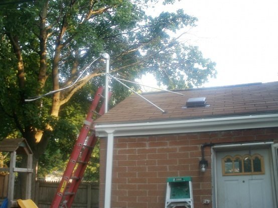
I would have installed the lightning arresters outside the house attached directly to a Grounding Electrode of some sort, such as the top of a ground rod, or through a grounding window of copper or aluminum on the exterior of the house. It is always better to have the arrestors as close to the Grounding Electrode System as possible and keep the Grounding Electrode Conductor as straight as possible. Any bend in the GEC should have as long a radius as practical. The stationary connectors could be mounted through a piece of aluminum angle iron using short barrel connectors. But then my time installing remote communications shelters from Tierra Del Fuego to Alaska made me a grounding fanatic. Our number one rule was to do everything practical to keep any form of stray energy out of the shelter.
-
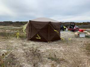
Were does your antenna lead in; such as coaxial cable, twin lead, window line, or ladder line; from the antenna enter the house. Do you have any route between the electrical service equipment at point 1 to the mast at point 3 that is not covered in concrete? When you say that your electrical service mast looks like the one in my picture does that include having 2 guy bars to resist bending forces from the weight of the Service Drop wires from the utility pole? I take it that your present electrical service mast is at point 1. Is the other service mast in the same place or close by? Is the utility pole to the South East? Is the street on the East side of the house? If you are willing you could give me an address or latitude & longitude so that I could look at the layout on Google Maps Satellite view. If you don't want to make that public you could send it to me in a private message or by E mail to hQoRrMnetd via gmail after you tune out the QRM from the prefix. You can send images direct to me if that helps. The remainder of the conversation should stay here on the reflector for peer review so others can point out any mistakes I might make.
-
Just so I get this clear the 20 feet you mentioned is the distance between your Electrical Service and the Electric Utility's Power Pole on the west? Cable companies always take the cheapest way out even when the results are dangerous. Is your interior water piping metallic? Is the new gas piping plastic? The flat dish thingy is the pressure relief valve that protects your home from a failure of the regulator that reduces the pressure from the transmission level down to the distribution level. That regulator may also reduce the pressure again because the pressure inside most homes is equivalent to that of a few inches of standing water. That is why the regulator is vented to the open air. If your home's gas fueled appliances were subjected to distribution pressure far too much gas would flow and a gas fueled structure fire is the likeliest outcome. The County does not get a say over the distribution of fuel gas. That is under control of whatever your state calls their utility regulatory agency. Since you do not have an earthquake threat in your area you do not need a Trembler Valve. It would still be a very good idea to have an excess flow valve installed. Excess flow valves will only permit the gas required by your gas appliances ti flow through it. It is adjusted to that flow at the time of installation. Any flow above that which the appliances would consume causes the valve to shut off the flow. You have used the word pole in 2 different places. To test for transfer I ask if the first one is a Utility Pole which carries electrical distribution wires and communications through you neighborhood. Just to keep things a little clearer I will refer to your antenna support "pole" as a Mast. Please explain what you mean by "attached to a eve of the house (6 ft level)?" The Eaves of a house are just below the roof line so an eave at a 6 foot level is not clear to me. The usual place to attach the house bracket of an antenna mast is to a reinforced pair of studs in the gable end of the attic or to a reinforcing piece immediately behind the Rake Board. Alternatively it can be attached to the top plate of the wall of the uppermost floor right underneath the drip edge at the horizontal edge of the roof. The gable end just beneath the ridge line is the preferred point of attachment because it is higher on the mast and provides more resistance to wind. It is rather rare to guy a house bracketed mast or tower unless it extends 10 or more feet above the point of attachment. As an aside there are rigid bars available in various lengths that are routinely used to stabilize Electrical Service Masts to which a service drop from the utility pole is attached above the roof when the direction of pull caused by the pull of the service drop cannot be countered by guy wires. They can also be used to stabilize an antenna mast without needing to run guy wires down off of the roof. Now back to your actual Grounding Electrode System (GES). To construct the GES for your antenna mast and antenna lead in conductor lightning arrester you have a few options. You could dig 31 inch deep trenches into which to bury the rods, bury 2 X 2 foot plates 30 inches below finished grade, or install a partial ground ring. You would connect the rods or plates to the antenna lead in entry protector and the antenna mast with a Grounding Electrode Conductor (GEC) of #6 American Wire Gauge (AWG) using termination methods which are suitable for use with the metals you are terminating the GEC to. That leaves you with the real need to bond the 2 GES to each other. You run a minimum #6 AWG copper conductor between the 2 GES to maintain the voltage between them as close to zero as possible. You don't need to worry if both of them rise to 1000s of volts as long as they stay in step and dance to the same tune. By that I mean that there has to be a difference in potential; which is measured in volts; which exceeds the withstand of the insulation in any attached wiring; to make a destructive current flow. Here is were you can save money and effort. The Ground Ring which I mentioned above is 20 or more feet of #2 AWG copper wire encircling the building at a minimum depth of 30 inches below finished grade. You will only be going 1/2 of the way around the hose so technically you will not be installing a Ground Ring electrode. Notice, though, that the minimum length of a ground ring is 20 feet in order to move it out from things like well houses and irrigation control sheds to make it long enough to be reasonable effective. Going part way around the house will be more than 20 feet so it will function better than a "Ground Ring" for a well or spring house would. Neither you nor the electrons care if it meets the code requirement for a "Ground Ring." What matters is that it provides enough soil contact area to allow the current to dissipate across the effected surface of the earth. So just install a #2 AWG GES bonding conductor, rather than the # 6 minimum required, at a depth of 30 inches between the 2 Grounding Systems. The Grounding Electrode for your antenna mast and antenna lead in conductor entry point will be the partial ground ring. when you connect it to the electrical service It will become part of that Grounding Electrode System. You will then use that one common Grounding Electrode System to ground your radio station. A way to make the partial Ground Ring much more effective is to substitute copper strap conductor for the round #2AWG wire that is called out in the National Electric Code. The cross sectional area of #2 copper is 0.0521 square inches. Do the math for the cross sectional area of the copper strap and buy the least expensive copper strap which exceeds the cross sectional area of the #2AWG copper wire. There are several sources of copper strap conductor, such as Georgia Copper and some roofing supply houses; copper is used as the material to flash slate and tile roofs. Georgia Copper is just a vendor that I know the name of off the top of my head. There are several others and it is definitely worth shopping around. Prices vary widely. Note: The partial ground ring must be terminated to one of the acceptable points of the Electrical Service Equipment. You cannot connect it to a driven rod or buried plate electrode because the GEC which connects either of those to the Service Equipment is too small to let the partial ground ring be fully effective. Use a long enough #2AWG copper to reach all the way to the service equipment. By definition the Service Equipment is the enclosure which contains the Service Disconnecting Means. That is the first Switch, Fused Pull Out, or Circuit Breaker which will open, meaning disconnect, all of the energized conductors which supply electrical power to the home. One thing that would help me fully understand your situation would be a picture of your Electrical Meter Base Enclosure, often called the meter pan or can, which is wide enough to include the meter and the ground beneath it along with the point were the conductors from the meter enter the house. With that if front of me I can fully describe were the partial ground ring will be connected to your service equipment. -- Tom Horne W3TDH

-
First things first. Electrical services are never grounded to a gas line because a lightning discharge flowing on gas piping is nearly certain to start a gas fed structure fire! Since you are in California you may have a trembler or excess flow stop valve on your gas line outside the building; or if your gas meter is inside it could be next to the meter. A trembler valve closes when it is shaken by the movement of the earth which accompanies an earthquake. Building codes refer to them as seismic shut-off valves. Excess Flow Valves close when there is a sudden increase of flow such as from a broken pipe or defective appliance. If you do not presently have either a trembler nor excess flow valve you should strongly consider having one installed. I would have both installed since a trembler valve will not respond to excess flow without ground movement. Why yes I do volunteer with the Department of Redundancy Department. Thank you for asking. Interior portions of fuel gas lines are required to be bonded to the electrical system ground but the National Electric Code (NEC) recognizes the Equipment Grounding Conductor (Green Wire) in the wiring to a gas appliance as serving that purpose. A separate bond wire is not required nor desirable. There are 2 Unions in your gas line on either side of your gas meter to permit it's removal for replacement or servicing. The one on the supply, street, side of the gas meter should be replaced with a Dielectric; that means electrically insulating; union. They can be exchanged 1 for 1 as long as the pipe thread sizes are the same as the existing conductive pipe union. The gas fitter can install the dielectric union at the same time he/she installs your new valve/s. Unless you have worked in the plumbing, air conditioning, or pipe fitting crafts installing the replacement dielectric union is NOT a do it yourself project. Fuel gas is nothing to fool around with. I am retired out of 45 years of service as a volunteer firefighter and emergency medical technician. I responded to 3 gas explosions during my service and in 2 of them the house was entirely destroyed. The reason for installing a dielectric union is to avoid lightning current equalizing across the surface of the earth via your interior gas piping. Now back to your grounding electrode system construction. It is important to note that driven rods are only one of several Grounding Electrodes recognized by the National Electric Code (NEC). Another electrode is a 2 foot square copper plate which is 0.06 inches thick. Plate electrodes shall be installed not less than 750 mm (30 in.) below the surface of the earth. Ground rods can be laid flat in a trench in soil were they cannot be driven. "where rock bottom is encountered at an angle up to 45 degrees, the electrode shall be permitted to be buried in a trench that is at least 750 mm (30 in.) deep." It is still required that 8 feet of rod be in contact with the soil. Most Amateur Radio Operators in locations as rocky as yours do not end up using driven rods for grounding. That is because their operating location is seldom immediately adjacent to the location of their electric Service Disconnecting Means. The reason that is important is that the Grounding Electrode System (GES) of the Electrical Service must be bonded to the GES of the Radio antenna and the antenna lead in lightning protector. So before I can advise you any further I would need to know how far apart those 2 locations are from each other. -- Tom Horne W3TDH
-
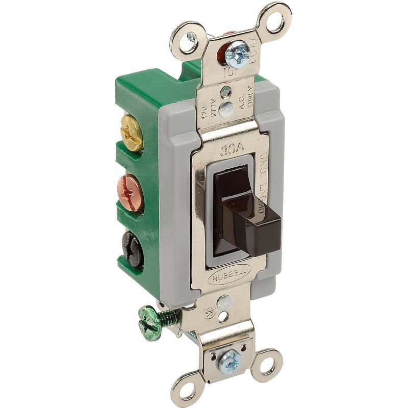
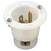
The Manual Transfer Switch would be used as an alternative way to recharge the site's back up battery array to full capacity. If severe weather, such as a damaging hail storm, put the solar array and windmill out of service the APRS beacon located at the site would report the loss of DC charging current for the battery array to the repeater committee members who are monitoring for such reports given the occurrence of that severe weather. A support team from the MARC Repeater Committee would go to the building that houses the KV3B North remote receiver for the 146.955 MHz repeater and the KV3B D-STAR repeater to determine how to keep some or all of the site's equipment in service. The team would determine whether the photovoltaic array or the wind generator could be rapidly returned to service. They would also check the state of charge of the battery array which stores the solar and wind power provided by those 2 outdoor power production systems. If restoring one or both of the on site power generation systems was not immediately doable then the utility AC electric supply to the converter charger for the batteries and the normal DC power to operate the site would be switched from it's building electrical system receptacle outlet to a dry (non-energized) fixed plug electrical inlet. Because of the small size of the circuit to be switched the transfer assembly would be made from regular electrical parts such as the ones shown in the attached photographs. Those include a Double Pole, Double Throw, Center Off Switch, a fixed plug inlet to except the cord from another AC power source, with the boxes and parts to put them together into a complete transfer assembly. Factory built transfer assemblies are not manufactured in such a small size. By throwing the switch to the down position; because that is the position customarily used for that purpose; the Charger Converter AC supply would then be connected to the inlet which will except an extension cord's receptacle end cord cap which is supplied by another source of AC power. The Generator used would have to run long enough to charge the battery array to it's maximum capacity. That would have to be repeated as often as needed until one or both of the alternate sources could be repaired and brought back on line, a suitable extension cord was run to an power outlet elsewhere in the building which is supplied by the building's emergency generator, or utility power was restored. Since access to the topmost roof of that building is controlled by security it might be possible to leave a small generator with an extended run tank on the roof and replenish the fuel and lubricant oil as often as needed to keep it running. If you think of the photovoltaic array as the belt and the wind generator as the suspenders then the alternative AC power inlet is a BIG safety pin that can make the waist of the pants tight enough to stay up. It's not elegant nor even convenient but it allows the wearer to keep working. -- Tom W3TDH
-
I don't know how I missed the station being on the second floor even though mine is as well. I had the coaxial cable entering up high on the house for years but I'm finally biting the bullet and running the coaxial cable up through the interior of my home inside rigid and flexible metallic (steel) conduit. The conduit will provide some shielding to the coaxial cable from magnetic fields generated by Lightning discharge. The only conductors which will run down the outside wall of the house are: The Grounding Electrode Conductor that will ground the antenna mast itself, and also the operating position's single point bonding busbar to the Grounding Electrode Array at that end of the house were the shack is. The coaxial cable from the multi band vertical mounted at the peak of one gable end of the house is my biggest challenge. I am ambivalent about how to route that coaxial cable down from the antenna to the shack. I'm very tempted to run the coaxial cable through an arrestor on the mast and inside the house to my shack. What I'm actually going to do is to run it on top of the copper strap Grounding Electrode Conductor which will run down the outside wall of the house from the antenna mast. I'll still have an arrestor on the antenna mast and I may bond the shield of the coaxial cable to the nearest Grounding Electrode at the bottom of that coaxial run just a few feet off the ground. That is were the coaxial cable will loop back up into the cable entry box. The Grounding Electrode Conductor will continue to the nearest electrode of the Grounding Electrode Array at that end of the house. The cable entry box will be at the front corner of that end of the house so that the cables will enter into the basement just below the first floor closet in which the cable raceway conduit will run on the inside of the house back up to the shack on the second floor. That is the way that we did it on towers when I was still working. 1 arrestor at the top of the tower, coaxial cable shield bonded to the tower every so many feet, arrestor at the base of the tower to take advantage of the grounding electrode system at the base of the tower, into a conduit box at the top of the non metallic conduit run to the communications shelter, out of the conduit run and up the outside of the shelter to the cable entry bulkhead, through which the shelter lightning arrestor was mounted, and then on to the equipment in the shelter. The biggest challenge may well be getting a hold of one 10 foot stick of 2" rigid steel conduit. I think that the steel conduit will do a better job of attenuating the magnetic field from a lightning discharge so that it will not induce as much current into the coaxial cable shield. At all of the coaxial connectors which are on the radio equipment at the operating position I'm going to install Polyphaser EMP protectors right on the equipment antenna ports. I' hoping that will help reduce the effects of having the shack on the second floor. Aluminum conduit I can get and I'm going to use a stick of that as the new mast for the tri-band vertical which now sits right at the ridge line. I'm hoping that 5 or 6 feet above the ridge will improve it's performance and maybe even keep it from setting off my smoke detectors. If my Son, Daughter in law, and Grand Child were not living here with us my shack would move to the basement. That was the plan before his job died in the pandemic. Jamison W3ESX I don't suppose that you have a practical way of getting your coaxial cables up to your shack through the houses interior? -- Tom W3TDH
-
First what are we trying to do in the entirety of the work. We want the coaxial cable to pass through a lightning arrester and then into the building to your radio operating position. The cable entry point is into the entry box through a bulkhead connector or through the arrestor itself. What that says to me is that the cable comes into the weather proof entry box by it's connection to arrestor or bulkhead threads. The arrestors themselves or the bulkhead connectors used to pass the cable through the wall of the box are all mounted through the bottom wall of the box. That markedly lessens the possibility of water intrusion through the penetrations. Notice: The smallest knockout opening in an electrical box is a nominal 1/2 inch and an actual 7/8ths inch. It is generally impractical to reduce those down to an actual 1/2 inch that will just fit the male threads on the outside or a female coaxial cable connection. From the inward cable end of the lightning arrestor, in the interior of the entry box, another piece of coaxial cable passes through the back wall of the box into a non metallic conduit nipple which ends at the inside of the wall. Through the same conduit nipple the operating position's Grounding Electrode Conductor will also pass into the entry box and continue down to the Grounding Electrode Array. It must be bonded to the metal of the entry box on it's way through. If you use grounding braid you will terminate that to the interior of the box and ground that bonding point and the box itself to the Grounding Electrode System. The Grounding conductors will be copper in the form of braid or strap. The braid will only be used indoors from the inside of the box to the single point grounding busbar at the operating position. From the outside of the box to the Grounding Electrode array near the antenna lead in entry box use copper strap conductor 4 inches wide. There are things that you need to be aware of when you use a ferrous metal enclosure such as the steel box shown in that video. The most important factor is that when a conductor passes through a ferrous metal to which it is not bonded the magnetic field created by the current flow will induce a current into the ferrous metal which will then create a magnetic field of it's own. That second magnetic field opposes the first one and creates counter EMF in the form of the opposing magnetic field. That is how you put impedance into an electric circuit. A coil of wire of a given size will have a characteristic impedance. If you place an iron core inside the magnetic field that will raise the impedance of the coil. To eliminate that effect, and all of the unwanted secondary effects that it might cause, install the lightning arrester through the wall of the steel box through a hole that is only large enough to let the threads go through. After removing any coatings such as paint and any surface corrosion, which is not visible until it has progressed into the metal beneath the surface, you apply anti oxidant paste for steel and put a stainless steel fender washer between the arrester and steel, and between the steel and the arrestor locking nut. You end up with one fender washer on each side of the steel with the threaded portion of the connector on one end of the arrestor passing through the fender washers and held in place by the thread nut on the other side. The fender washers provide a greater contact area between the arrestor body and the mild steel of the box while isolating the dissimilar metals from direct contact. Again you will use an anti corrosion paste which is suitable for the metals you are using between the fender washers and the steel wall of the box. Should you want to duck much of that work then use an Aluminum box. Since the box and the arrester block are both aluminum all of the dissimilar metal issues go away. Since the Aluminum of the box is not magnetic it is unlikely to add unwanted impedance to the Grounding Electrode Conductor path. To duck the cost of an aluminum box you can buy a plastic box instead. You will need to install a copper grounding busbar in the back of the box and you will need to connect it to the Grounding Electrode Array with a low impedance conductor. The aluminum box may be the most expensive but it is the least work. To make the penetrations water tight use sealing nuts or washers on the outside of the box and o-rings on the inside of the box. Do not use washers on both the inside and outside of the box as that will break the bonding connection between the box and the arrestor. By using bulkhead barrel connectors anywhere the coaxial cable enters the enclosure you overcome the connector's size not being able to pass through the hole that is only as large as the outside of the bulkhead connector or arrestor threads. If you are determined to pass unbroken coaxial jacket through the wall of the box you need a cord connector that has a sealing gland through which the coaxial connector will pass and that will make an air and watertight seal once the gland nut is tightened down. That would provide you with some additional choices which in my not humble opinion you do not need. If you place the cord connector gland nut and seal over the coaxial cable prior to attaching the connector you will increase the work you do and have reduced options in changing the cable routing later. -- Tom W3TDH
-
I'm truly sorry that I lost track of this thread and am only now answering the information that you provided. Since you need to bond the 2 Grounding Electrode Systems to each other anyway you have an opportunity to markedly improve the overall grounding of your home. First Thing: Do NOT run the bonding conductor through the house if you can possibly avoid that. Inviting the energy of a lightning strike to travel through your house to equalize the voltage on the 2 Grounding Electrode Arrays is not a great idea. It sharply raises the likelihood of a side flash from the bonding conductor to the interior wiring and plumbing systems. The energy from a side flash is more than hot enough to kindle a fire. If you run the inter grounding array conductor outside the home then it can itself become a Grounding Electrode. The name that the US National Electric Code gives for the electrode you can make is a "Ground Ring." A ground ring is 20 or more feet of #2 AWG bare copper conductor, encircling the building, and buried at a depth of 30 inches or more. Your not going to encircle your entire home so your bonding conductor will not be an actual "Ground Ring" but if you look at the first requirement that it be 20 or more feet; think a well or spring house; you will see that doing the half circle that you need to interconnect the 2 separate Grounding Electrode Arrays does offer the same actual ground contact as a ring around a smaller building would. The difference between your half ring and an inter array bonding conductor is that a Ground ring is 3 common wire sizes larger and is buried at least 2 foot deeper than a bonding conductor would be. That does raise the material cost and the amount of labor. Do yourself a favor and rent a trenching machine to dig the trench. They are not terribly expensive to rent and make the job much easier. Check what the cost of #2 bare copper is in your area and compare that to the cost of copper strap conductor between 2 and 6 inches wide. The widest one you can afford is the best choice. Because the voltage rise of a lightning discharge is so very fast it has the same impedance characteristics as a high frequency AC current. For the same cross sectional area the strap conductor will have a much lower impedance because much more of the conductor's cross sectional area will carry the current. The strap conductor gets connected to a rod electrode in each array by sandwiching it between 2 copper plates formed to fit closely around the rod to maximize the contact area between the Strap conductor and the driven rod electrode. Those plates can be purchased ready made but with a little patience you can make your own. Stainless Steel hardware is used to hold the 2 plates on either side of the copper strapping. Emery cloth or fine metal "Sand Paper" is used to remove any surface corrosion from the contact surfaces at the attachment or splicing points. A copper contact sealing paste such as KOPR-SHIELD is used to coat the contact surfaces to exclude water, prevent oxidation, and improve conductivity. Georgia Copper is one source for the strap conductor. It can sometimes be purchased more cheaply at a roofing supply house because the roofing industry uses a lot more copper sheeting strips as flashing for slate roofs than the radio equipment market would ever need. If you have any questions please ask. -- Tom W3TDH
-

Suggest a rig to replace Yaesu FT-857D for EMCOMM
W3TDH replied to W3TDH's topic in Emergency communications
The major challenge that we have encountered with the Icom IC-5100 is that it's data port is only connected to it's D-Star mode circuitry. It cannot be used for analog digital. If there is no D-STAR node available you cannot send digital traffic to an analog station. If you try to use the microphone connector the band width is hobbled by the audio circuitry between the microphone jack and the discriminator and deviation circuits. Perhaps it might be possible to bring more direct connections out on the microphone jack if you could fit the two separate audio pathways on the eight wires of the microphone cord. I would be willing to give up the microphone up down frequency selection functions to have the analog broadband modes possibility. It might be simpler to replace the digital jack with a DIN connector that would make both D-Star and analog data transfer possible It is easy to see why ICOM would rather that you use the D-STAR modulation pathway for data and I would think that would work fine under internet and electrical utility normal operation. But if either go by-by D-STAR data exchange would be reduced to point to point; and only between D-STAR radios; during the very disaster that we are trying to assist with. -- Tom W3TDH -
Suggest a rig to replace Yaesu FT-857D for EMCOMM
W3TDH replied to W3TDH's topic in Emergency communications
That is the reason that I'm looking for a replacement for the Yaesu FT-857D. A transceiver with similar capabilities would be a complete backup to a primary VHF / UHF radio and also an additional VHF / UHF operating position if that was the needed use. -- Tom W3TDH -
The Repeater Committee is considering my suggestion that we add an AC power inlet and manual transfer switch to the remote receiver site which does not have a generator supported electrical supply. That would allow a generator at ground level to supply the repeater's Battery Charger-conditioner long enough to recharge the battery bank if the Solar Array and wind generator were to fail. Think severe ice storm or hail. We may place the inlet in the stairwell near the Fire Department Emergency Electrical Circuit outlet. That supply takes the form of a simple conduit run in the stair well with an inlet plug at the bottom and a receptacle outlet on each floor. We would need to have adapters for the Fire Department's 20 ampere locking receptacle and inlet but I had planed to include those in the Montgomery County Auxiliary Communications Service's standard generator accessory kit accessories list. Since No is the easiest word to utter in the English language I have devised an alternative. There is a conduit run to the building's roof from the repeater equipment which is not yet in use. We could reduce the exposure to theft or tampering by locating the generator inlet on the roof and running the inlet wiring down to the repeater with the Photovoltaic array's wiring. If the elevators were not available a Honda EU1000i could be hauled up by rope using a tyrolean traverse if the emergency power team were short staffed. With the use of such a small generator it should be possible to just carry it up the stairs if there are 3 or 4 people on the team. Since there would be other heavy equipment to carry; such as tools, a service monitor, and an extended run generator fuel tank; it might take 3 or more people to carry it all. -- Tom W3TDH
-
Jameson W3ESX First let me introduce myself and provide a little of my background. I'm retired out of over 45 years in the electrical craft. I spent a part of my career installing communications shelters from Tierra Del Fuego up to Alaska and from French Frigate Shoals to Tucson Arizona area. The number of shelters I managed the installation of is over 100. The most important part of the installations was usually the Grounding Electrode System. Many of the shelters which I oversaw were self contained and self powered. Since that doesn't bear on your project I'll leave it there. A Ground Rod is a Grounding Electrode. Three Driven Rod Electrodes spaced 2X their length apart, bonded to each other, and then connected to a Ground Busbar or cable entry bulkhead is a Grounding Electrode System. This leads to several questions. Were is your Electrical Meter and Service Equipment in Relation to the Antenna entry? Is it on the end of the house shown in the diagram or is it on the other end. Is there any particular reason that you want to use a steel enclosure for your lightning arresters? Will any other wire of any description enter your home through your grounding bulkhead. (That is the conductive metal panel of grounding busbar were you will be mounting your arresters.) I ask these question because the answers have a large effect on the effectiveness of your grounding system. -- Tom Horne W3TDH
-
Jim K3MRI Yes that is exactly what I had in mind. It avoids the bad reactions that deploying into the operational area engender and yet makes those who do so the nearest resource of it's kind. The objective in preparing to do this would be in assembling a team with a truly diverse set of skills to provide the widest range of capabilities. Each offered service would have to have two fully qualified lead operators. One or both of them would have to cross train the remainder of the team in how to support the deployment of that resource to the affected area as needed. Emergency Management is now talking about fuel for generators and operating grocery stores as community lifelines. One example of a very supportive deliverable would be to provide basic connectivity so that electronic payment could be available for buying such necessities. An inexpensive long range wireless connection out of the quieted area would be one way to be a lot of help. We connect the EOC 1st, Hospital 2nd, Grocery 3rd, bank branch 4th, and then connect one or more otherwise operational fuel stations... I don't know how to find my way around in an IP stack nor program a IP network. But I can take a laptop, network transceivers, antennas, and support to some effective point. I could install the transceiver antenna support. You have to be able to keep the antennas aimed without attendance. And then aim the antennas at the other points to be served, and adjust them until the software likes the signal. I could do that to as many points of use as were wanted by the officials in situ without messing with any ARES or other services engaged in direct radio support. I cannot imagine a hospital not wanting to have at least basic email service restored nor an EOC for that matter. And if what is needed is to install some basic alarm transmission path between the fire alarm dispatch office and fire stations those same techniques would work there as well. We would certainly need 2 or more operators who could program and control the network but those of us who had cross trained on the node installation tasks would be real force multipliers to that effort. That is just one example. Imagine how welcome a transportable repeater and a mast to get it's antenna 50 feet above whatever it was sitting on might be. We would need to be able to set that mast up on different types of surfaces even if that involved a star drill and a 5 pound drilling hammer. [Side Note: "So John Henry say to the shaker. Now shaker you better pray. Cause I'm swinging 20 pounds from my hips on down, if I miss twill be your burying day! If I miss twill be your burying day!" The shaker pulled a wooden toggle handle on the end of a leather thong wrapped around the drill bit so it would turn and shook the bit between blows to bring the chips out of the hole. the shaker often worked crouching in the face of the tunnel with the driller back far enough to get a good swing. They drilled holes were the blasters needed them and when the fuse was lit the blaster would shout "Fire in the hole!"] -- Tom Horne W3TDH
-
I think that there is a workable approach that I haven't seen written about. Instead of deploying stage a close by as you can without entering the area that does not have communications services. Set up to support the in situ Ops and listen for the establishment of a resources net or it's equivalent. Then inform them that you have brought that 120 foot of replacement tower they're lamenting the loss of with you. You have several 40 foot tilt ups with dual band J-Poles and the accessories to make them really versatile. [So & So say's he needs relief.] You have a 2 person team who could be en route in half an hour and on location in; give totally honest number. They won't have expected you but if you show up with a broad set of skills and a willingness to TAKE direction rather than give it It could be a good thing. Somehow you have to avoid bringing trouble; meaning "That Guy." The one that always knows a better way and has absolutely no humility about telling the in situ leadership that their DOING IT WRONG;! You also need to bring some real support equipment that you are willing to set up and let others use. None of this "We're the pros from Dover. Just get out of our way" BS! One that that can be provided with a modest investment is 5G long range linking and mesh net support. The 5G links can not be Amateur Radio! Hospitals and EOCs need encryption and Amateur Radio cannot give it to them. Long haul wireless internet can make a lot of friends very quickly. Being very judicious about who gets what kind of on ramp to that Freeway is critical. The first Bozo that goes looking for his daily dose of "those" videos can down your system by taking up all of the effective bandwidth. Those who train would do that kind of support would have to be willing to learn enough to cancel that idiot's access in jig time. There are programs that can be deployed that provide browser based email on a text in and text out basis. Anyone who needs something else has to call a control point RADO and get someone on the incident management team to agree that they need it. No One needs that artistic border that makes their email look like binder paper and turns their entire message into a bandwidth hog. -- Tom Horne W3TDH The hands that hold the nozzle fit a shovel handle to. Get live patients to adequate care. Put the wet stuff on the red stuff. It isn't that hard. "It is dangerous on the face of it, tackling a burning building. The risks are plain…consequently, when a man becomes a fireman, his act of bravery has already been accomplished. Everything else is his daily duty." Edward F Croker, Chief Engineer Commanding, Fire Department of the City of New York. Circa 1910.
-
Not so fast! The genesis of our hobby is the International Telegraph Code as initially devised by Friedrich Clemens Gerke for use on the German railways. Telegraphy is the first electronic communication. Beginning with Wheatstone's needle telegraph. Followed by Morse's single wire telegraph using Alfred Vail's code which he devised for the Morse Printing Telegraph Company. This became known as the Morse Code which Morse himself had no part in devising but took credit for anyway. -- Tom Horne
-
The Pup Generator Runs again. If you have wanted to have an inverter generator but cannot afford to buy one of the good Commercial Off The Shelf (COTS) offerings you may want to consider Home Brewing one. I have no interest of any kind in any materials vendor which I mention in this posting. I suppose that most Hams who are thinking about an Inverter Generator realize that the most expensive part of one is the Inverter. It is possible to find one that is not going to put an unbearable hole in your back account balance. Vehicle Salvage yards can be a great source of parts for your project. Many Service Vehicles are fitted with Inverters of various capacities to run power tools at job sites or on board the service vehicle itself. Service Vehicles also get involved in collisions, some of which result in a total loss. Focus your searching on salvage yards that specialize in service vehicles or in trucks and vans. Watch Craig’s List, Freecycle Network, Nextdoor free items lists and other such sources for the small engine you need. You may also be able to get an alternator from such sources. Free Lawnmowers are a great source of 4-7 HP engines. The distinct sub assemblies which will be needed to build your less expensive inverter generator will be: Mounting frame including; Protective carry frame Mounting plate Drive enclosure Vehicle alternator with 150 amperes or greater capacity Universal cooling fan for alternator, Alternator will be turning in the opposite direction from that for which the OEM cooling fan was designed, Drive engine of 5 brake horsepower rating or higher Drive assembly consisting of; Flywheel pulley mounted on engine drive shaft, industrial A pattern, match shaft size, Drive pulley mounted on Alternator drive shaft, industrial A pattern, match shaft size, Drive belt, 36 inch, industrial A pattern, Wiring harness and output connector for alternator, Pure Sign-wave Inverter, capacity appropriate to the amount of DC current available or to your budget. Using modified sign-wave output inverters will cause improper operation of some loads which can then damage the equipment which they supply or are a part of. Some loads can be directly damaged or destroyed by a modified sign-wave supply. The first thing that you will make or buy for this is a mounting plate. If the plate were only for mounting it would be easier to fabricate but since it also serves as the adjusting bracket for the drive belt tension it is probably the most work of the whole effort. If you are not up for cutting the mounting slots in the plate it can be obtained; along with many of the other parts, from the https://theepicenter.com/emergency-power/homemade-generators/vertical-belt-drive.html. Second is the frame on which the mounting plate will be fastened. U Channel Construction strut is a good choice of material because many of the fittings can be purchased at a home center or Electrical Supply House. Enclosure materials can be perforated metal sheeting, Expanded Mesh, and 1/8 inch opening Hardware cloth. I favor the hardware cloth because of it’s lower cost and lighter weight. Use angle metal to cover the edges. The remaining steps of the assembly process are: Fit the universal cooling fan and the small RPM multiplier pulley to the alternator shaft, The OEM cooling fan will not be effective because the alternator will be turning in the opposite direction than the OEM fan was designed for. Fit the larger flywheel pulley on the engine shaft, Mount the mounting plate on the frame, Mount the alternator and the engine on the mounting plate, Adjust the positions of the engine and alternator to tension the A pattern industrial drive belt, Adjust the pulley mounting on the shafts to align them at the same distance from the mounting plate, Make that distance as close as practical to the bearings of the engine and the alternator to avoid placing avoidable leverage on the shaft. Connect the alternator wiring harness, Mount the alternator power connection, Mount the Inverter to the frame, Connect alternator output to inverter supply terminals, Install enclosure material, Note: If you don’t add an Inverter you will have built a “Pup Generator” That is a “Rectified Output Engine Alternator Set” that will produce copious amounts of DC current. That can be directly connected to the Starting, Lighting, and Ignition (SLI) Battery of a vehicle to supply all of the current that could possibly be needed to run several radio stations in or adjacent to the vehicle.
-
I raced Tech Dories and Lightnings and enjoyed it a lot but after seeing one near miss with a would be rescuer nearly running down a lightning crew member while going to the more visible capsized boat I went to one of the Engineering professors at Boston University and suggested that it would be a very worthwhile project to have fourth year students design propeller guards for the guard boat's outboard motors. One volunteer was operating an ex Coast Guard Motor Lifeboat and was totally offended that anyone thought he should have propeller guards on his inboard engine driven propellers. I was able to bring him right into line by taking a trip with him to an active Coast Guard Lifeboat station. The first thing I managed to have him see was that the newer Motor Life Boat sitting in the launch cradle on it's marine railway had propeller guards on the boat. While we were there the station was alerted for a child being blown out to see on an air mattress. I don't think I'll ever forget the loud haler calling out "Ready Crew Man your boat! Ready Crew Man your boat!" Five Coast Guardsman pounded past us on the wooden walkway to the head of the marine railway and released the Motor Lifeboat so that gravity would accelerate it into the sea. My companion could see those rather large propellers turning as the Lifeboat went down it's marine railway track. The props had to be at 3/4s of maximum revolutions when that boat went into the water at a fairly high speed in order to maintain post launch control of the boat. He saw those props turning from up close and became an instant convert. He led the way in getting the other guard boat operators to except propeller guards. I believe that propeller guards are a readily available accessory from most outboard boat motor manufacturers now but I don't know if that is true of all brands. A couple of those volunteers did impressive conversions of their larger boats to water jet propulsion with the only impellers inside the hull. Everybody in that lightning club was grateful for the change in attitude. A wonderful side effect of the 2 boats converting to water jet propulsion was that since the owners were members of the Coast Guard Auxiliary the Coast Guard came up with some hose, hand-line nozzles, extension tube applicators with fog heads, and a small monitor nozzle so that they had some firefighting capability. Since the 2 jets on each boat had their own drive engine the helmsman could keep the boat in place with one jet and flow 250 Gallons of water per minute to the fire manifold with the other engine. I was quite impressed and so were the 2 owners who had gone to such effort to convert to water jet propulsion. -- Tom W3TDH
-
If you were selecting a new radio for use in a transportable station focused on EMCOMM which one would you choose. My personal favorite to date has been the Yaesu FT-857D because it is "DC to Daylight:" that is that it will work any amateur band between 160 Meters and 70 Centimeters with the exception of the 1.25 Meter band. Even though I always used a dual band VHF and UHF mobile rig with it the redundancy seemed valuable to me and I did end up using it for that a couple of times. I found the separable control head useful to reduce operating table clutter. My choice for a transportable table has been a 30" by 30" plastic table with folding legs so I didn't want to have to fit every thing on the desk top. I suppose if I use a rack case instead of the well padded shipping case that might not be an issue. One new consideration is that I would like to be able to do near continuous duty digital modes, such as VERA & PACTOR at 100 watts. I think that will require some sort of medium power amplifier to combine with the radio so that both would be running at ~1/3rd of their nominal maximum output power but don't get too hung up on that. There no longer seems to be any "All Band" transceiver rated 100 watts at near the weight and size of the Yaesu FT-857D. The ICOM 7100 is a little larger and heavier. It cannot be configures as a single unit. The controller cannot be mounted flat on a transportable stations front panel. But so far it is the only comparable I have identified. I have used the ICOM 7100 for hospital nets because it is what the commercial radio installers chose for the hospital's radio station. I'm not allergic to it in any sense so don't think I'm ruling it out. The Yaesu FT-897 has a very similar form factor to the FT-857D but it has no VHF UHF capability and the operating controls do not separate from the RF unit. If I used the FT-897 for the transportable station's HF capability I think I would need to add an amplifier/s for the dual band portable so that it could function as a VHF & UHF base station or mobile radio. I include the possibility of 2 separate amplifiers because if I needed to do a lot of digital with the combination the only dual band amplifier I've found, the Mirage BD-35, cannot produce a mobile unit's full output and certainly not at 100% duty cycle. If I would have to carry 2 amplifiers for the mobile VHF UHF radio and 2 for the VHF UHF portable, in order to have the desirable redundancy, things begin getting a bit too heavy bulky and complex. If I separate the HF radio into one rack case and the Mobile VHF - UHF radio into another it might make it more manageable but it would raise the price of a commercial air ticket by another $50. The combined radio and power kits would already cost $100 per ticket. I think I have a pretty good grasp of the accessory and antenna issues so please confine suggestions to the radio itself. Thanks in advance for any ideas. -- Tom Horne W3TDH
-
Individual equipment for those just starting in EMCOMM would be my first priority. A couple of other things I would consider would be ~10 to 25 Yaesu FT-60 Portable radios with Byonics Tinytrak modems. If I could get the Byonics All In One as a 2way busy channel detecting APRS tracker I would look into those. They are fairly watertight and self contained. I would want to add an external shrouded, water proof, center off double throw switch to select the 2 profiles. If it were possible an external covered Emergency switch which would take 2 motions of a gloved finger to open the cover and throw the switch would be great. Within the present configuration that would have to be integrated into the double pole switch in some way. A completely covered switch in series with the Emergency pole of the Double pole switch would meet that requirement without requiring an electronic redesign of the transmitter. I've already tested the present model inside the next size smaller pelican case and it does fit. If Byonics could add external connectors for power/charging and Data IO that would be fantastic. Since short Winlink messages can be sent over APRS it would give the individual ARES operator a lot of options.That would be the other reason to have a transceiver in lieu of a transmit only design. For any routine traffic the operator could send a short Winlink message without needing the voice channel to make their report. It might make things less exciting for the Net Control Operators but I don't see that as a bad thing. Just imagine the field operators at any event being able to indicate, without first having to get the net control operators attention, that they had urgent or Emergency traffic for them. No more waiting anxiously for the channel to become available. They trip the appropriate profile and net control calls them. That would provide a much smoother information flow by indicating to net control who should have their attention next. They need an ambulance for a patient who is unresponsive, not breathing, in heat stroke, bleeding out, Femur fracture... They can get the channel immediately. Heat exhaustion etc the other profile would indicate non emergency traffic to ask that they be next in the Net Control Operators' cue. I emphasize that in the absence of Emergency or Priority traffic for Net Control the field operators APRS transceiver would be left with the profile selection switch in the Center Off position -- Tom Horne W3TDH
-
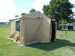
I'd find the best deal I could on 2400 watt inverter generators and LiFePh4 batteries and provide them to our younger ARES members so as to help them be ready to deploy. I might also include a complete 11' x 11' tan Standard Integrated Command Post System (SICPS) tent from military surplus with a "boot wall." The boot wall would make it possible to attach a weather resistant access to a vehicle over a fairly wide range of types. If I could find one in good condition I'd add a single unit shelter heat and cooling unit. Those include a Generator to power the system. Those would make a good support item for an ARES Mutual Assistance Team (ARES MAT). -- Tom Horne W3TDH
-
The TS-480HX is what I was saving up for when Kenwood dropped the 480 model line. My concern is that buying a modal that has already been discontinued would mean that service or parts support would be unavailable rather soon. That is why I though that an amplifier with a wider range of drive wattage that would reduce the amplifier output as the drive power was lowered might be a good answer. With the right drive range a 300 Watt amplifier could coast along quite happily at 100 watts output and 100% duty cycle. -- Tom W3TDH
-
 Did I miss it or did you explain the mode of failure of the operating shelter? Tom W3TDH
 -
Isn't the FTDX101MP that huge contesting rig with the built in panadapter that weighs in at nearly 30#? Not exactly an EMCOMM friendly rig. What I didn't see in your answer is how I reduce the workload on the radio / amplifier combination that you are talking about so that the 2 used together will stand up to modes that cause a near 100% duty cycle. 10 watts output on a Yaesu FT-857 is great but doesn't that leave the amplifier running at full rated power output? That would not be likely to stand up to a very high duty cycle. Does anyone know of an amplifier that takes a wider exciter power range and varies the output power with the exciter power. I want to have both the transceiver and the amplifier running at not more than ~1/3 of their respective maximum power output. I already have the Yaesu FT-857 radio. I think that it's form factor is a very good choice for EMCOMM. My plans include a remote antenna coupler, rather than an antenna tuner niether in the radio nor at the operating location. With me it's nearly a religious tenet that you match the feed to the antenna rather than matching the transmitter to the feed line. The other thing that makes me avoid using antenna tuners which are part of the Transceiver is that the range of Impedance which they can match is much lower than an external tuner or a remote coupler. Repeating I want the combination to be able to run at 1/3 of it's maximum output so that it will better put up with a higher duty cycle that approaches 100%. -- Tom W3TDH


10 newly posted or edited posts
-
 Christmas on the Rhine Boat Trip Started
 -

-

-

-
 Last Minute Items Started
 -
Volunteer Update Emails Started
-
-
 Flashlights left at MCM Check-In Started
 -
-
Quick Menu
- Ham Community - Homepage
- Ham Boutique - Get your farkle
- Ham Census - Shape the future of Ham Radio
- Ham Weblinks - Curated links
- Ask the Elmers - Direct access
- Ham Quizzes - Keeping you sharp
- Ham Tutorials - Learn from the best
- Ham Speakers - Give a talk, find a speaker
- Ham Volunteers - Organize and volunteer
- Support - For site or boutique problems
Ham Mega Pad (XXXL)
Ham Word Cloud Pad (XL)
Ham Codes, Signs, Words (Medium)
Ham Band Edges mousepad (Small)
Ham Alliance